A
MINI PROJECT REPORT
ON
“LASER SECURITY SYSTEM USING ARDUINO”
ABSTRACT
Security is a prime
concern in our day –today life. Everyone wants to be as much as secure as
possible.
As this project mainly deals with the design and
implementation of a Laser security
system using Arduino for detecting intruders
A study regarding the design and implementation of an
Arduino- based security system using laser light was made to help users secure their
homes due to increasing crimes if something or someone passed through between
the laser light and light dependent resistor, the buzzer will automatically
make a sound. During the test, it shows that the prototype is 80 percent
successful. The researchers were able to determine
and utilize the functionalities of the laser, light
dependent resistor, and the Arduino. Therefore, the researchers conclude that
this research is a success.
The prime Advantage of using the laser system is that
intruder is unaware of the fact that a security system is installed in the
entry points like door and windows. Since laser rays can travel long distance
without scattering effect. It is also visible only at source and incident point
otherwise invisible
It is among the
most Affordable security system that can be used for indoors as well as
outdoors
CHAPTER-1
INTRODUCTION:
In this project, we have designed Laser Light Security System
Using Arduino with Alarm with the application of Laser Diode Module KY-008. The
project idea revolves around creating a security system. Whenever any object
will obstruct the LASER ray and the buzzer alarm will start ringing.
This project can be implemented anywhere, not only buildings or premises but many precious things like jewellery, diamonds, precious antique items in the museum, etc. Many other things are also secured using such an invisible LASER beam. Many people secure their home, office, shops, warehouses, etc. With the LASER beam security system.
CHAPTER-2
Block Diagram

CHAPTER-3
CIRCUIT DIAGRAM

CHAPTER-4
Components
Voltage
What
is voltage?
Voltage is a measure of the electric force
available to cause the movement or flow of electrons. Thus, voltage in itself
implies no movement of electrons, but the potential to cause electrons to move.
Voltage measurements of direct current
When an electric force is available to cause
the movement of electrons, a voltmeter is used to measure the potential. When
that potential is unchanging, it is said to be a direct current or DC
potential. DC electricity typically comes from a battery, but may come from a
filtered, rectified power supply. More on rectification and filtering later.
Voltage measurements of alternating current
When an electrical force is available to
cause the movement of electrons, it can sometimes not be measured accurately
because the value is changing instant-by-instant. In a typical generator, for
example, it can be changing in value between -110Volts and +110 volts in a
sinusoidal (sine wave) fashion. Voltage that changes instant-by-instant, such
as your household power, is called AC or Alternating Current.
In these cases, a rectified value is
extracted and filtered in order that an average, 'positive' voltage value can
be measured. More on the mechanism of rectification later but know that this is
a method of converting AC into DC electricity.
Voltage:
The difference of Electric potential which
exists between two points of conduction carrying a constant of one Ampere. When the power dissipates between these
points in one watt.
The unit of Voltage “Volt”
= V
nV =
Nano Volt = 10-9 = 1/1000000000
µV =
Micro Volt = 10-6 = 1-1000000
mV =
Mille Volt = 10-3 = 1/1000
V =
Volt = 1
KV =
Kilo Volt = 103 = 1000
MV =
Mega Volt = 106 = 1000000
GV =
Giga Volt = 109 = 1000000000
Current Conversion:
1000 µ V
= 1 mV
1000mV
= 1 V
1000 V =
1 KV
1000 KV = 1
MV
1000 MV = 1 GV
There are two types of
Voltage
AC Voltage & DC Voltage.
RESISTORS
A resistor is a
passive electrical component with the primary function to limit the flow of
electric current.
In almost all electrical networks and
electronic circuits they can be found. The resistance is measured in ohms. An
ohm is the resistance that occurs when a current of one ampere passes through a
resistor with a one volt drop across its terminals. The current is proportional
to the voltage across the terminal ends. This ratio is represented
by Ohm’s law,

Fig 3.0 resister
Resistor
Symbols:

Fig 3.1 resister
There are two main circuit
symbols used for resistors. All resistors have two terminals, one connection on each
end of the resistor.
Resistor units:
The unit or resistance is
the Ohm, Ω and resistor values may be seen quoted in terms of Ohms - Ω,
thousands of Ohms or kilohms - kΩ and millions of Ohms, mega ohms, MΩ.
Resistor
Types:
The first major categories into which the
different types of resistor can be fitted is into are
1.fixed resistors
2.variable resistors

Fig
3.2 resister
Surface-mount resistors are usually tiny black
rectangles, terminated on either side with even smaller, shiny, silver,
conductive edges. These resistors are intended to sit on top of PCBs, where
they're soldered onto mating landing pads

Fig 3.3 pcb
coding the Color Bands
Through-hole, axial resistors usually use the
color-band system to display their value. Most of these resistors will have
four bands of color circling the resistor, though you will also find five band
and six band resistors.
|
Color |
Digit |
Multiplier |
Tolerance (%) |
|
Black |
0 |
100(1) |
|
|
Brown |
1 |
101 |
1 |
|
Red |
2 |
102 |
2 |
|
Orange |
3 |
103 |
|
|
Yellow |
4 |
104 |
|
|
Green |
5 |
105 |
0.5 |
|
Blue |
6 |
106 |
0.25 |
|
Violet |
7 |
107 |
0.1 |
|
Grey |
8 |
108 |
|
|
White |
9 |
109 |
|
|
Gold |
|
10-1 |
5 |
|
Silver |
|
10-2 |
10 |
|
(none) |
|
|
20 |
Four Band Resistors
In the standard four band resistors, the
first two bands indicate the two
most-significant digits of the resistor's value. The third band is
a weight value, which multiplies the
two significant digits by a power of ten. The final band indicates the tolerance of the resistor.

Fig 3.4 color
code
Five and Six Band Resistors
Five band resistors have a
third significant digit band between the first two bands and the multiplier band.
Five band resistors also have a wider range
of tolerances available.
Six band resistors are basically five band
resistors with an additional band at the end that indicates the temperature
coefficient.

Fig 3.5 resistor color code calculation
RESISTOR PROPERTIES
Ø Low Temperature Coefficient of Resistance (TCR)
Ø Noise
Ø Protection against influences from the environment
Ø Electrical resistivity of the material
Resistors and its uses:
A few examples include delimit electric current, voltage division, heat
generation, matching and loading circuits, control gain, and fix time
constants. They are commercially available with resistance values over a range
of more than nine orders of magnitude. They can be used to as electric brakes
to dissipate kinetic energy from trains, or be smaller than a square millimeter
for electronics.
Ø Blower resistor
Ø Shunt resistor
Ø Heater resistor
Ø Pull up resistor / Pull down
resistor
Ø Resistor for LED
Ø Power resistor
Ø Resistors in series
Ø Resistors in parallel eltandard
Switches
|
Type of Switch |
Circuit Symbol |
Example |
|
ON-OFF A simple on-off switch. This type can
be used to switch the power supply to a circuit. When used with mains electricity this
type of switch must be in the live wire, but it is better to use a
DPST switch to isolate both live and neutral.
|
|
 SPST toggle switch |
|
(ON)-OFF A push-to-make switch returns to its
normally open (off) position when you release the button, this is shown by
the brackets around ON. This is the standard doorbell switch.
|
|
 Push-to-make switch |
|
ON-(OFF) A push-to-break switch returns to its
normally closed (on) position when you release the button.
|
|
 Push-to-break switch |
PUSH BUTTON:
A Push Button switch is a type of switch which
consists of a simple electric mechanism or air switch mechanism to turn
something on or off.
The "push-button" has
been utilized in calculators, push-button telephones, kitchen appliances, and various other mechanical
and electronic devices, home and commercial.
In industrial and commercial applications, push buttons can be
connected together by a mechanical linkage so that the act of pushing one
button causes the other button to be released. In this way, a stop button can
"force" a start button to be released. This method of linkage is used
in simple manual operations in which the machine or process has no electrical circuits for control.

Fig 4.0
Special Switches
Light-emitting diode
.

Fig 4.1
Blue, green, and red LEDs; these can be
combined to produce most perceptible colors, including white. Infrared
and ultraviolet (UVA) LEDs are also available.
LED schematic symbol
.
A light-emitting-diode (LED) is
a semiconductor diode that emits light when an electric current is applied in the forward direction of the
device, as in the simple LED circuit. The effect is a form of electroluminescence where incoherent and narrow-spectrum light is emitted from the p-n junction in a solid state material.
LEDs are widely used as indicator lights on
electronic devices and increasingly in higher power applications such as
flashlights and area lighting. An LED is usually a small area (less than 1
mm2) light source, often with optics added directly on top of the
chip to shape its radiation pattern and assist in reflection.[2][3] The color of the emitted light
depends on the composition and condition of the semi conducting material used,
and can be infrared, visible, or ultraviolet. Besides lighting, interesting
applications include using UV-LEDs for sterilization of water and
disinfection of devices,[4] and as a grow light to enhance photosynthesis in plants.[5]
Buzzer
Basics - Technologies, Tones, and Drive Circuits
There are many choices for
communicating information between a product and the user. One of the most
common choices for audio communication is a buzzer. Understanding some of the
technologies and configurations of buzzers is useful during the design process,
so in this blog post we will describe typical configurations, provide example
buzzer tones, and present common drive circuit options.
Magnetic and Piezo Buzzers
The two most common
technologies used in buzzer designs are magnetic and piezo. Many applications
use either a magnetic or a piezo buzzer, but the decision regarding which of
the two technologies to use is based upon many different constraints. Magnetic buzzers operate at lower voltages and higher
currents (1.5~12 V, > 20 mA) compared to piezo buzzers (12~220 V, < 20
mA), while piezo buzzers often have greater maximum sound
pressure level (SPL) capability than magnetic buzzers. However, it should be
noted that the greater SPL available from piezo buzzers requires larger
footprints.
In a magnetic buzzer, a
current is driven through a coil of wire which produces a magnetic field. A
flexible ferromagnetic disk is attracted to the coil when the current is
present and returns to a "rest" position when the current is not
flowing through the coil. The sound from a magnetic buzzer is produced by the
movement of the ferromagnetic disk in a similar manner to how the cone in
a speaker produces sound. A magnetic buzzer is a current driven
device, but the power source is typically a voltage. The current through the
coil is determined by the applied voltage and the impedance of the coil.

Fig 4.1

Fig 4.2
Construction of a typical piezo buzzer
A piezo buzzer differs from
a magnetic buzzer in that it is driven by a voltage rather than a current. A
piezo buzzer is modelled as a capacitor while a magnetic buzzer is modelled as
a coil in series with a resistor. The frequency of the sound produced by both
magnetic and piezo buzzers can be controlled over a wide range by the frequency
of the signal driving the buzzer. A piezo buzzer exhibits a reasonably linear
relationship between the input drive signal strength and the output audio power
while a magnetic buzzer's audio output declines rapidly with a decreasing input
drive signal.
What is solder?
|
|
|
Reels of solder |
Solder is an alloy (mixture) of tin and lead, typically
60% tin and 40% lead. It melts at a temperature of about 200°C. Coating a
surface with solder is called 'tinning' because of the tin content of solder.
Lead is poisonous and you should always wash your hands after using solder.
Solder for electronics use contains
tiny cores of flux, like the wires inside a mains flex. The flux is corrosive,
like an acid, and it cleans the metal surfaces as the solder melts. This is why
you must melt the solder actually on the joint, not on the iron tip. Without
flux most joints would fail because metals quickly oxidise and the solder
itself will not flow properly onto a dirty, oxidised, metal surface.
The best size of solder for electronics
is 22swg (SWG= standard wire gauge).
Desoldering
At some stage you will probably need to desolder a joint
to remove or re-position a wire or component. There are two ways to remove the
solder:
|
|
|
Using a desoldering pump (solder
sucker) |

1. With a desoldering pump (solder
sucker)
- Set the pump by pushing the spring-loaded
plunger down until
- it locks.
- Apply both the pump nozzle and the tip of your
soldering iron to the joint.
- Wait a second or two for the solder to melt.
- Then press the button on the pump to release
the plunger and suck the molten solder into the tool.
- Repeat if necessary to remove as much solder
as possible.
·
The pump will need emptying
occasionally by unscrewing the nozzle.
|
|


Solder remover wick
Fig 5.0
2. With solder remover wick (copper braid)
- Apply both the end of the wick and the tip of
your soldering iron to the joint.
- As the solder melts most of it will flow onto
the wick, away from the joint.
- Remove the wick first, then the soldering
iron.
- Cut off and discard the end of the wick coated
with solder.
After removing most of the solder from the joint(s) you may be able to remove
the wire or component lead straight away (allow a few seconds for it to cool).
If the joint will not come apart easily apply your soldering iron to melt the
remaining traces of solder at the same time as pulling the joint apart, taking
care to avoid burning yourself.
Soldering iron
For electronics work the best type is one powered by
mains electricity (230V in the UK), it should have a heatproof cable for
safety. The iron's power rating should be 15 to 25W and it should be fitted
with a small bit of 2 to 3mm diameter.
Jump wires
The jump wires for bread boarding can
be obtained in ready-to-use jump wire sets or can be manually manufactured. The
latter can become tedious work for larger circuits. Ready-to-use jump wires
come in different qualities, some even with tiny plugs attached to the wire
ends. Jump wire material for ready-made or home-made wires should usually be 22
AWG (0.33 mm²) solid copper, tin-plated wire - assuming no tiny plugs are to be
attached to the wire ends. The wire ends should be stripped 3/16" to
5/16" (approx. 5 mm to 8 mm). Shorter
stripped wires might result in bad contact with the
board's spring clips (insulation being caught in the springs). Longer stripped
wires increase the likelihood of short-circuits on the board. Needle-nose
pliers and tweezers are helpful when inserting or removing wires, particularly
on crowded boards.
Differently colored wires and color coding discipline are
often adhered to for consistency. However, the number of available colors is
typically far less than the number of signal types or paths. So typically a few
wire colors get reserved for the supply voltages and ground (e.g. red, blue,
black), some more for main signals, while the rest often get random colors.
There are ready-to-use jump wire sets on the market where the color indicates
the length of the wires; however, these sets do not allow applying a meaningful
color coding schema.
Printed circuit board (PCB)

Fig 5.1

Fig 5.2
PCBs are boards whereupon electronic
circuits have been etched. PCBs are rugged, inexpensive, and can be highly
reliable. They require much more layout effort and higher initial cost than
either wire-wrapped or point-to-point constructed circuits, but are much
cheaper and faster for high-volume production. Much of the electronics
industry's PCB design, assembly, and quality control needs are set by standards
that are published by the IPC organization.
ABOUT THE PCB
Printed wiring Board, an essential part of
total electronic packaging system, which provides interconnection between
components, and physical support for the whole assembly. Various types and
configuration of components are mounted on Printed wiring board to make the
board functional as an electronic device.
The printed wiring boards are classified as
follows:
i.
Single sided
ii.
Double sided
iii.
Multi-layer
iv.
Flexible
The single sided PCB is the simplest, and has
the conductor pattern printed only on
one side. The components are inserted and mounted on the other side of the PCB.
The double
sided PCB has conductor patterns on both
sides and components are mounted on one side, while in a multilayer PCB has
several layers of conductors which are sand witched together.
The PCB consists of conductor tracks of
Solder plated copper and required size of Holes (or plated through holes) for
mounting various components as per design.
The basic substrate for the PCBs is made up
of one of the following insulating materials:
i.
Paper phenol
ii.
Glass epoxy
iii.
Glass polyamide
iv.
Ceramic
The flexible boards are generally made up of
polyamide substrate.
The Ceramic substrate is generally used in
Defense applications where the ceramic components are used.
SOLDER MASK: Solder mask is applied on the
Bare Printed Circuit board for avoiding solder coating on unwanted conductor
tracks during wave soldering and preventing conductor tracks from exposing to
atmosphere. Normal conformal coating materials are
1.
Acrylic
2.
Polyurethane
3.
Silicone
4.
Paraxylylene
5.
Epoxy
These coatings are applied by means of dipping,
spraying, brushing or vacuum deposition depending upon material used.
Surface-mount technology
Surface-mount technology (SMT) is a method for constructing electronic circuits in which the components (SMC or Surface Mounted Components)
are mounted directly onto the surface of printed circuit boards (PCBs). Electronic devices so made are
called surface-mount devices or SMDs. In the industry it has
largely replaced the through-hole technology construction method of fitting components
with wire leads into holes in the circuit board.
LASER SECURITY SYSTEM USING ARDUINO
An SMT component is usually
smaller than its through-hole counterpart because it has either smaller leads
or no leads at all. It may have short pins or leads of various styles, flat contacts, a
matrix of solder balls (BGAs), or terminations on the
body of the component.
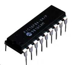
Microcontrollers
Microcontroller
is a single chip microcomputer made through VLSI fabrication. A microcontroller
also called an embedded controller because the microcontroller and its support
circuits are often built into, or embedded in, the devices they control. A
microcontroller is available in different word lengths like microprocessors
(4bit,8bit,16bit,32bit,64bit and 128 bit microcontrollers are available today).

Fig 6.0
Microcontroller Chip
You
can find microcontrollers in all kinds of electronic devices these days. Any
device that measures, stores, controls, calculates, or displays information
must have a microcontroller chip inside. The largest single use for
microcontrollers is in automobile industry (microcontrollers widely used for
controlling engines and power controls in automobiles). You can also find
microcontrollers inside keyboards, mouse, modems, printers, and other
peripherals. In test equipment’s, microcontrollers make it easy to add features
such as the ability to store measurements, to create and store user routines,
and to display messages and waveforms. Consumer products that use
microcontrollers include digital camcorders, optical players, LCD/LED display
units, etc. And these are just a few examples.
1) A
microcontroller basically contains one or more following components:
Central processing
unit(CPU)
Random Access Memory(RAM)
Read Only Memory(ROM)
Input/output ports
Timers and Counters
Interrupt Controls
Analog to digital
converters
Digital analog
converters
Serial interfacing ports
Oscillatory circuits
2) A
microcontroller internally consists of all features required for a computing
system and functions as a computer without adding any external digital parts in
it.
3)
Most of the pins in the microcontroller chip can be made programmable by the
user.
4) A
microcontroller has many bit handling instructions that can be easily
understood by the programmer.
5) A
microcontroller is capable of handling Boolean functions.
6)
Higher speed and performance.
7)
On-chip ROM structure in a microcontroller provides better firmware security.
8 )
Easy to design with low cost and small size.
Microcontroller
structure
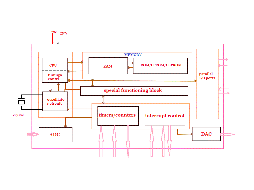
The
basic structure and block diagram of a microcontroller is shown in the fig
(1.1).

Fig
6.1micro controller structure
Microcontroller Structure
CPU
CPU is the brain of a
microcontroller. CPU is responsible for fetching the instruction, decodes it,
then finally executed. CPU connects every part of a microcontroller into a
single system. The primary function of CPU is fetching and decoding
instructions. Instruction fetched from program memory must be decoded by the
CPU.
Memory
The
function of memory in a microcontroller is same as microprocessor. It is used
to store data and program. A microcontroller usually has a certain amount of
RAM and ROM (EEPROM, EPROM, etc) or flash memories for storing program source
codes.
Parallel input/output ports
Parallel
input/output ports are mainly used to drive/interface various devices such as
LCD’S, LED’S, printers, memories, etc to a microcontroller.
Serial ports
Serial
ports provide various serial interfaces between microcontroller and other peripherals
like parallel ports.
Timers/counters
This
is the one of the useful function of a microcontroller. A microcontroller may
have more than one timer and counters. The timers and counters provide all
timing and counting functions inside the microcontroller. The major operations
of this section are perform clock functions, modulations, pulse generations,
frequency measuring, making oscillations, etc. This also can be used for
counting external pulses.
Analog to Digital Converter
(ADC)
ADC
converters are used for converting the analog signal to digital form. The input
signal in this converter should be in analog form (e.g. sensor output) and the
output from this unit is in digital form. The digital output can be used for
various digital applications (e.g. measurement devices).
Digital to Analog Converter
(DAC)
DAC
perform reversal operation of ADC conversion. DAC convert the digital signal
into analog format. It usually used for controlling analog devices like DC
motors, various drives, etc.
Interrupt control
The interrupt control used
for providing interrupt (delay) for a working program. The interrupt may be
external (activated by using interrupt pin) or internal (by using interrupt
instruction during programming).
Special functioning block
Some
microcontrollers used only for some special applications (e.g. space systems
and robotics) these controllers containing additional ports to perform such
special operations. This considered as special functioning block.
Comparison
between Microprocessor and Microcontroller
The
main comparison between microprocessor and microcontroller shown in fig (1.2)
Advantages
of Microcontrollers
The
main advantages of microcontrollers are given.
a)
Microcontrollers act as a microcomputer without any digital parts.
b)
As the higher integration inside microcontroller reduce cost and size of the
system.
c)
Usage of microcontroller is simple, easy for troubleshoot and system
maintaining.
d)
Most of the pins are programmable by the user for performing different
functions.
e)
Easily interface additional RAM, ROM, I/O ports.
f)
Low time required for performing operations.
Disadvantages
of Microcontrollers
a)
Microcontrollers have got more complex architecture than that of
microprocessors.
b)
Only perform limited number of executions simultaneously.
c)
Mostly used in micro-equipment’s.
d)
Cannot interface high power devices directly.
Applications
Microcontrollers
are widely used in modern electronics equipment’s. Some basic applications of
microcontroller is given below.
a)
Used in biomedical instruments.
b)
Widely used in communication systems.
c)
Used as peripheral controller in PC.
d)
Used in robotics.
e)
Used in automobile fields.
Arduino
Arduino is an open-source platform used for building
electronics projects. Arduino consists of both a physical programmable circuit
board (often referred to as a microcontroller) and a piece of software, or IDE (Integrated Development Environment)
that runs on your computer, used to write and upload computer code to the
physical board.
The Arduino platform has become quite popular with people just starting out with electronics, and for good reason. Unlike most previous programmable circuit boards, the Arduino does not need a separate piece of hardware (called a programmer) in order to load new code onto the board -- you can simply use a USB cable. Additionally, the Arduino IDE uses a simplified version of C++, making it easier to learn to program. Finally, Arduino provides a standard form factor that breaks out the functions of the micro-controller into a more accessible package.

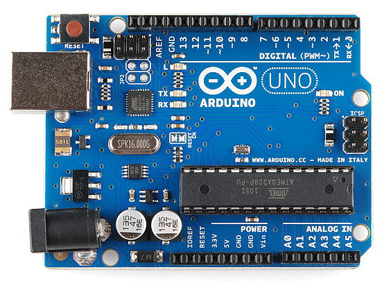
Fig 7.0 uno
This is an Arduino Uno
The Uno is one of the more popular boards in
the Arduino family and a great choice for beginners. We'll talk about what's on
it and what it can do later in the tutorial.
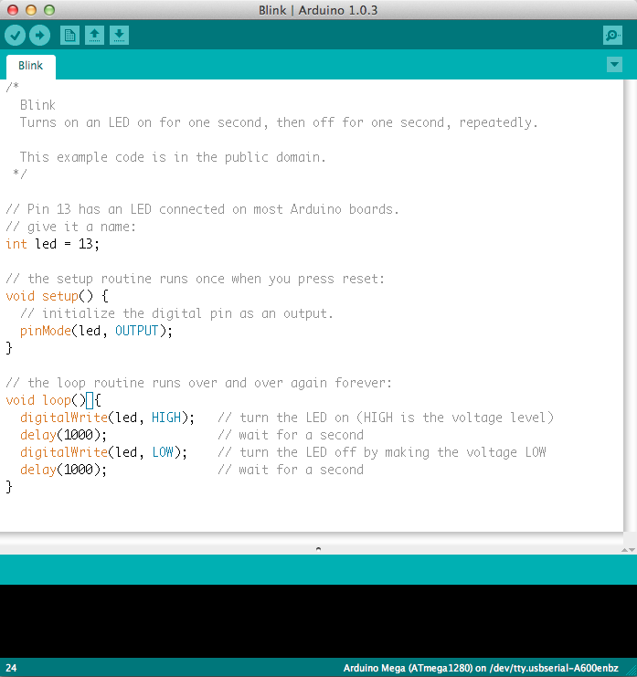
Believe it or not, those 10 lines of code are
all you need to blink the on-board LED on your Arduino. The code might not make
perfect sense right now, but, after reading this tutorial and the many more
Arduino tutorials waiting for you on our site, we'll get you up to speed in no
time
The Arduino hardware and software was
designed for artists, designers, hobbyists, hackers, newbies, and anyone
interested in creating interactive objects or environments. Arduino can
interact with buttons, LEDs, motors, speakers, GPS units, cameras, the
internet, and even your smart-phone or your TV! This flexibility combined with
the fact that the Arduino software is free, the hardware boards are pretty
cheap, and both the software and
hardware are easy to learn has led to a large
community of users who have contributed code and released instructions for a huge
variety of Arduino-based projects.
For everything from robots and a heating pad hand warming blanket to honest fortune-telling machines, and even a Dungeons and Dragons
dice-throwing gauntlet, the Arduino can be used as the brains behind almost any electronics
project.

This is a screenshot of the Arduino IDE.
There are many varieties of Arduino boards (explained on the next page) that can be used for different purposes.
Some boards look a bit different from the one below, but most
Arduinos have the majority
of these components in common:

Fig 7.1
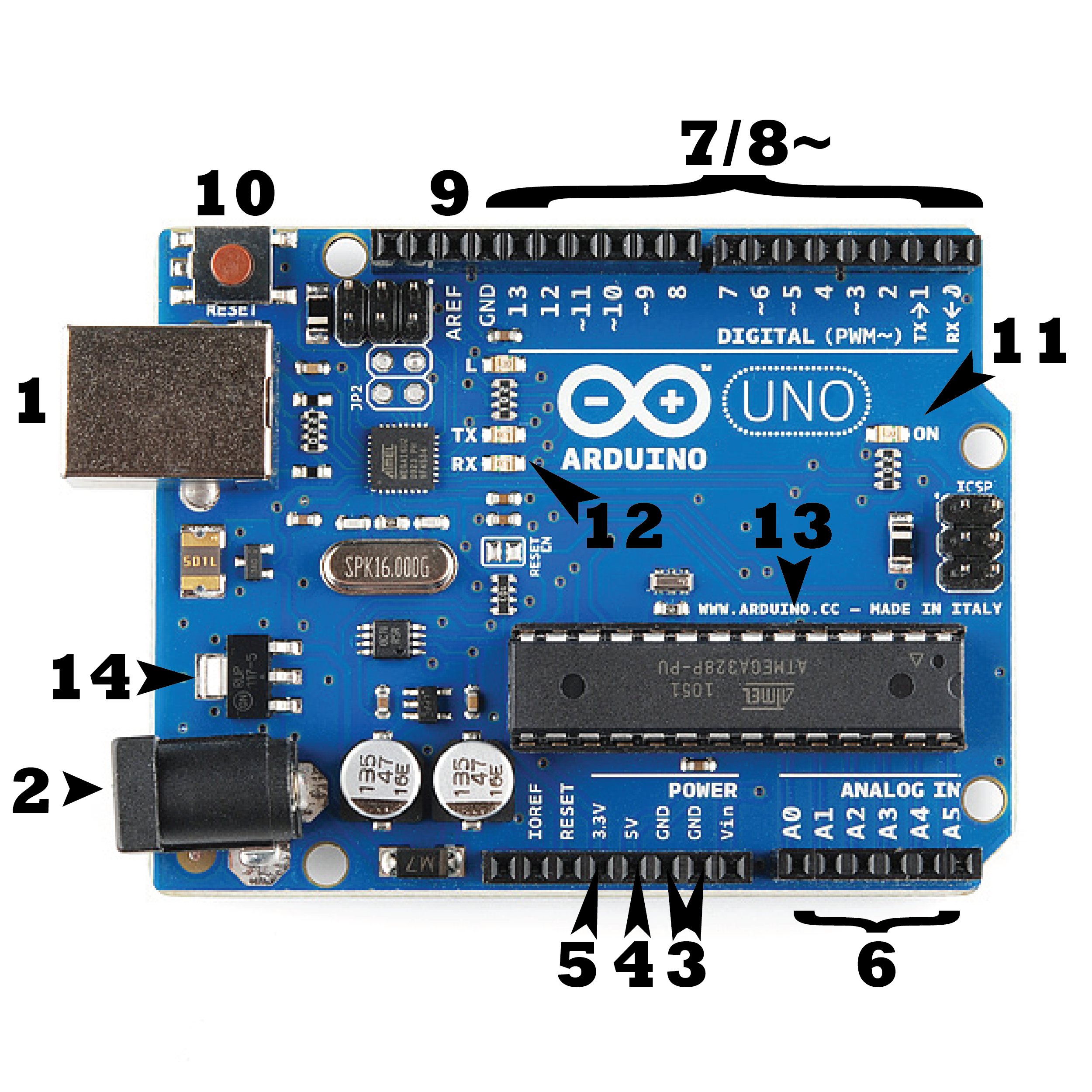
Power (USB / Barrel Jack)
Every Arduino board needs a way to be
connected to a power source. The Arduino UNO can be powered from a USB cable
coming from your computer or a wall power supply (like this) that is terminated in a barrel jack. In the
picture above the USB connection is labeled (1) and the barrel jack is
labeled (2).
The USB connection is also how you will load
code onto your Arduino board. More on how to program with Arduino can be found
in our Installing and Programming Arduino tutorial.
NOTE: Do NOT use a power supply greater than 20
Volts as you will overpower (and thereby destroy) your Arduino. The recommended
voltage for most Arduino models is between 6 and 12 Volts.
Pins (5V, 3.3V, GND, Analog, Digital, PWM,
AREF)
The pins on your Arduino are the places where
you connect wires to construct a circuit (probably in conjunction with a breadboard and some wire. They usually have black plastic ‘headers’
that allow you to just plug a wire right into the board. The Arduino has
several different kinds of pins, each of which is labeled on the board and used
for different functions.
·
GND (3): Short for ‘Ground’. There are several GND
pins on the Arduino, any of which can be used to ground your circuit.
·
5V (4) & 3.3V (5): As you might guess, the 5V pin supplies 5
volts of power, and the 3.3V pin supplies 3.3 volts of power. Most of the
simple components used with the Arduino run happily off of 5 or 3.3 volts.
·
Analog (6): The area of pins under the ‘Analog in’
label (A0 through A5 on the UNO) are Analog in pins. These pins can read the
signal from an analog sensor (like a temperature sensor) and convert it into a digital value that we
can read.
·
Digital (7): Across from the analog pins are the digital
pins (0 through 13 on the UNO). These pins can be used for both digital input
(like telling if a button is pushed) and digital output (like powering an LED).
·
PWM (8): You may have noticed the tilde (~) next to
some of the digital pins (3, 5, 6, 9, 10, and 11 on the UNO). These pins act as
normal digital pins, but can also be used for something called Pulse-Width
Modulation (PWM). We have a tutorial on PWM,
·
but for now, think of these
pins as being able to simulate analog output (like fading an LED in and out).
·
AREF (9): Stands for Analog Reference. Most of the
time you can leave this pin alone. It is sometimes used to set an external
reference voltage (between 0 and 5 Volts) as the upper limit for the analog
input pins.
Reset Button
Just like the original Nintendo, the Arduino
has a reset button (10). Pushing it will temporarily connect the reset
pin to ground and restart any code that is loaded on the Arduino. This can be
very useful if your code doesn’t repeat, but you want to test it multiple
times. Unlike the original Nintendo however, blowing on the Arduino doesn't
usually fix any problems.
Power LED Indicator
Just beneath and to the right of the word
“UNO” on your circuit board, there’s a tiny LED next to the word ‘ON’ (11).
This LED should light up whenever you plug your Arduino into a power source. If
this light doesn’t turn on, there’s a good chance something is wrong. Time to
re-check your circuit!
TX RX LEDs
TX is short for transmit, RX is short for
receive. These markings appear quite a bit in electronics to indicate the pins
responsible for serial communication. In our case, there are two places on the
Arduino UNO where TX and RX appear -- once by digital pins 0 and 1, and a
second time next to the TX and RX indicator LEDs (12). These LEDs will
give us some nice visual indications whenever our Arduino is receiving or
transmitting data (like when we’re loading a new program onto the board).
Main IC
The black thing with all the metal legs is an
IC, or Integrated Circuit (13). Think of it as the brains of our
Arduino. The main IC on the Arduino is slightly different from board type to
board type, but is usually from the AT mega line of IC’s from the ATMEL
company. This can be important, as you may need to know the IC type (along with
your board type) before loading up a new program from the Arduino software.
This information can usually be found in writing on the top side of the IC. If
you want to know more about the difference between various IC's, reading the
datasheets is often a good idea.
Voltage Regulator
The voltage regulator (14) is not
actually something you can (or should) interact with on the Arduino. But it is
potentially useful to know that it is there and what it’s for. The voltage
regulator does exactly what it says -- it controls the amount of voltage that
is let into the Arduino board. Think of it as a kind of gatekeeper; it will
turn away an extra voltage that might harm the circuit. Of course, it has its
limits, so don’t hook up your Arduino to anything greater than 20 volts.
Laser Diode Module KY-008:
Laser Transmitter module KY-008 for Arduino
emits a dot-shaped, red laser beam.
The KY-008 Laser transmitter module consists
of a 650nm red laser diode head
and a resistor. Handle with caution, do not
look directly into the laser head.
The specification of Laser Transmitter Module
KY-008 is as follows:
Operating Voltage – 5V
Output Power – 5mW
Wavelength – 650nm

Fig 8.0 Ldr
Operating Current – less than 40mA
Working Temperature – -10°C ~ 40°C [14°F to
104°F]
Dimensions – 18.5mm x 15mm [0.728in x
0.591in]
LDR (LIGHT DEPENDENT
RESISTOR):
The
controlling of lights and home appliances is generally operated and maintained
manually on several occasions. But the process of appliances controlling
may cause wastage of power due to the carelessness of human beings or unusual
circumstances. To overcome this problem we can use the light-dependent resistor
circuit for controlling the loads based on the intensity of light. An LDR or a
photoresistor is a device that is made up of high resistance semiconductor
material. This article gives an overview of what is LDR.

Fig 8.1 Ldr
light-dependent
resistor circuit and its working:
The
working principle of an LDR is photoconductivity, that is nothing but an
optical phenomenon. When the light is absorbed by the material then the
conductivity of the material reduces. When the light falls on the LDR, then the
electrons in the valence band of the material are eager to the conduction band.
But, the photons in the incident light must have energy superior than the
bandgap of the material to make the electrons jump from one band to another
band (valance to conduction).
CHAPTER-5
Working
Working of the Laser Light Security System Using Arduino
The project basically works on the principle
of interruption. If by any means the LASER light is interrupted the alarm will
start unless it is reset with push-button. The laser is a concentrated light
source that puts out a straight beam of light of a single colour.

Fig 9.0 LDR tx and rx
The LDR is sensitive to light and puts out a
voltage when the laser light hits it. When the laser beam is interrupted and
can’t reach LDR, its voltage output changes, and eventually the alarm will
ring.
Circuit:

Fig 9.1 circuit
diagram
CHAPTER-6
PROGRAM
Code
const int triggeredLED = 7;
const int triggeredLED2 = 8;
const int RedLED = 4;
const int GreenLED = 5;
const int inputPin = A0;
const int speakerPin = 12;
const int armButton = 6;
boolean isArmed = true;
boolean isTriggered = false;
int buttonVal = 0;
int prev_buttonVal = 0;
int reading = 0;
int threshold = 0;
const int lowrange = 2000;
const int highrange = 4000;
void setup(){
pinMode(triggeredLED, OUTPUT);
pinMode(triggeredLED2, OUTPUT);
pinMode(RedLED, OUTPUT);
pinMode(GreenLED, OUTPUT);
pinMode(armButton, INPUT);
digitalWrite(triggeredLED, HIGH);
delay(500);
digitalWrite(triggeredLED, LOW);
calibrate();
setArmedState();
}
void loop(){
reading = analogRead(inputPin);
int buttonVal = digitalRead(armButton);
if ((buttonVal == HIGH) && (prev_buttonVal == LOW)){
setArmedState();
delay(500);
}
if ((isArmed) && (reading < threshold)){
isTriggered = true;}
if (isTriggered){
for (int i = lowrange; i <= highrange; i++)
{
tone (speakerPin, i, 250);
}
for (int i = highrange; i >= lowrange; i--)
{
tone (speakerPin, i, 250);
}
digitalWrite(triggeredLED, HIGH);
delay(50);
digitalWrite(triggeredLED, LOW);
delay (50);
digitalWrite(triggeredLED2, HIGH);
delay (50);
digitalWrite(triggeredLED2, LOW);
delay (50);
}
delay(20);
}
void setArmedState(){
if (isArmed){
digitalWrite(GreenLED, HIGH);
digitalWrite(RedLED, LOW);
isTriggered = false;
isArmed = false;
} else {
digitalWrite(GreenLED, LOW);
digitalWrite(RedLED, HIGH);
tone(speakerPin, 220, 125);
delay(200);
tone(speakerPin, 196, 250);
isArmed = true;
}
}
void calibrate(){
int sample = 0;
int baseline = 0;
const int min_diff = 200;
const int sensitivity = 50;
int success_count = 0;
digitalWrite(RedLED, LOW);
digitalWrite(GreenLED, LOW);
for (int i=0; i<10; i++){
sample += analogRead(inputPin);
digitalWrite(GreenLED, HIGH);
delay (50);
digitalWrite(GreenLED, LOW);
delay (50);
}
do
{
sample = analogRead(inputPin);
if (sample > baseline + min_diff){
success_count++;
threshold += sample;
digitalWrite(GreenLED, HIGH);
delay (100);
CHAPTER-7
ADVANTAGES
The
circuit, construction and setup for the Laser Security System is very simple.
If used with a battery, the laser security system can work even when there is a
power outage.
Dis
advantages:
The laser security
system works only if the laser is obstructed. If the intruder passes without
obstructing the laser, it is considered as a failure.
In order to secure a larger area, we need more lasers and corresponding
sensors.
Applications
jewellery, diamonds, precious antique items in the museum, etc. Many
other things are also secured using such an invisible LASER beam. Many people
secure their home, office, shops, warehouses, etc.
CHAPTER-8
CONCLUSION
Buzzers are a simple and inexpensive means of
providing communication between electronic products and the user. Piezo and
magnetic buzzers are used in similar applications with the primary differences
being that magnetic buzzers operate from lower voltages and higher currents
than their piezo buzzer counterparts, while piezo buzzers offer users higher
SPLs in generally larger footprints. Buzzers configured as indicators require
only a dc voltage to operate but are limited to a single audio frequency of
operation, whereas transducers
require external circuitry, but provide a
wider range of audio frequencies
CHAPTER-9
RECOMMENDATIONS
The proponents recommend the following based
on findings:
· A laser security system can enhance the security system installed
in an area.
· This project can also provide safety to other people in terms of
other aspects. The researchers recommend the following for further improvement
of the system:
· Improve the content of the system by making it automated.
· Use more efficient LDRs that can handle large amounts of the
intensity of light received.
· It is
better to improve the electrical components for future researchers regarding
this topic to increase its accuracy in detecting motion and also, to widen its
range.
CHAPTER-10
REFERENCES
[1] H. Kant, M. Sharma, Y. Singh, “Laser Security Alarm.” (2015-16).
[2] V. Karri and J. S. D. Lim, “Method and Device to Communicate via
SMS After a Security Intrusion,” 1st International Conference on Sensing
Technology, Palmerstone North, New Zealand, (2005) November 21-23.
[3] Y. Zhao and Z. Yet, “Low cost GSM/GPRS BASED wireless home
security system,” IEEE Trans. Consumer Electron, vol. 56, no. 4, (2007)
January, pp. 546-567. [3]
[4] Z. Bing, G. Yun Hung, L. Bo, Z. Gangway, and T. Tina, “Home
Video Security Surveillance,” Info-Tech and Info net, 2001, Proceedings, ICII
2001-Beijing. 2001 International Conference, vol. 3, pp. 202-208.

Comments
Post a Comment